Emulating I2S on STM32F103
8th November, 2026I like building audio and music related things. Recently, I’ve acquired an INMP441 as an addition to my slowly growing rack of electrical and digital components. The INMP441 is cheap digital microphone that uses transmits data via I2S.
With this and an STM32F103C8, I set out to make an LED react to audio as a “Hello, World!” of sorts.
Method
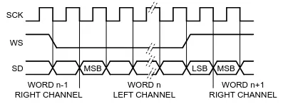
I2S is not available on low and medium density STM32 devices1, but is easily emulated, as AN5086 demonstrates. With the INMP411, which transmits a 32-bit dataframe comprising 24-bits of audio data, the challenge is aligning the data as it comes.
Here’s the approach:
- Configure SPI in receive-only master mode
- Configure the DMA to continuously read the SPI Data Register
- Use SCK to trigger a timer
- Use another channel on the same timer to generate the WS signal
- Process the DMA buffer in halves
Step 1 - Configure SPI in receive-only master mode
In receive-only master mode (RXONLY = 1, MSTR = 1), SCK generation begins as soon as SPE=12. The SPI transmitter is also disabled. This is handy as there is 1 GPIO pin less to configure and trasmission doesn’t have to be handled.
SPI2->CR1 = SPI_CR1_MSTR |              /* Master mode */
            SPI_CR1_SSM | SPI_CR1_SSI | /* Force NSS high */
            SPI_CR1_DFF |               /* 16-bit Dataframe */
            SPI_CR1_RXONLY |            /* Receive-only mode */
            (4 << SPI_CR1_BR_Pos);      /* SPI SCK Prescaler: 32 */
SPI2->CR2 = SPI_CR2_RXDMAEN;            /* enable DMA for RX */
SCK Frequency
I’ve chosen SPI2 here because the pins are physically closer to where the microphone is on the breadboard. SPI2 uses the APB1 clock, which has been configured to 36MHz. The prescaler is 32, giving an SCK frequency of 1.125Mhz.
Step 2 - Configuring the DMA
The DMA is configured in circular mode to continuously transfer data from
SPI_DR to rx_buf, the buffer that is used later for processing.
volatile uint16_t rx_buf[RX_BUF_LEN] = {0};
// ...
DMA1_Channel4->CPAR = (uint32_t)&SPI2->DR; /* read from SPI_DR */
DMA1_Channel4->CMAR = (uint32_t)rx_buf;    /* write to rx_buf */
DMA1_Channel4->CNDTR = RX_BUF_LEN;
DMA1_Channel4->CCR = DMA_CCR_MINC |    /* Increment rx_buf index */
                     DMA_CCR_CIRC |    /* Circular mode */
                     DMA_CCR_PL_1 |    /* High priority */
                     DMA_CCR_PSIZE_0 | /* 16-bit Peripheral */
                     DMA_CCR_MSIZE_0 | /* 16-bit Memory */
                     DMA_CCR_TCIE | /* Enable transfer complete interrupt */
                     DMA_CCR_HTIE | /* Enable half transfer interrupt */
                     DMA_CCR_EN;    /* Enable DMA */

NVIC_EnableIRQ(DMA1_Channel4_IRQn); /* Enable IRQ */
NVIC_SetPriority(DMA1_Channel4_IRQn, 1); /* Set IRQ priority */
The ISR sets status flags and returns.
void DMA1_Channel4_IRQHandler(void){
  uint32_t full_transfer_complete = DMA1->ISR & DMA_ISR_TCIF4;
  if(full_transfer_complete){
    DMA1->IFCR |= DMA_ISR_TCIF4;
    flags |= FLAGS_HALF_A_COMPLETE;
    return;
  }
  uint32_t half_transfer_complete = DMA1->ISR & DMA_ISR_HTIF4;
  if(half_transfer_complete){
    DMA1->IFCR |= DMA_ISR_HTIF4;
    flags |= FLAGS_HALF_B_COMPLETE;
    return;
  }
}
Step 3 - Configuring the timer to generate WS
The timer is configured to starts on the falling edge of SCK. The PWM signal that drives WS is inverted, starting low to send the left channel first.
#define WS_PERIOD 64     /*!< 64 SCK cycles for every stereo data-word */
#define WS_PRESCALER 64  /*!< Prescale TIM1 to the same frequency as SPI_SCK */
#define WS_DUTY_CYCLE 32 /*!< 50% duty cycle */
// ...
TIM1->ARR = WS_PERIOD - 1;
TIM1->PSC = WS_PRESCALER - 1;
TIM1->BDTR |= TIM_BDTR_MOE; /* TIM1 is an advance timer, this is needed to
                               enable output */
TIM1->SMCR |= (6 << TIM_SMCR_SMS_Pos) | /* Slave mode: Trigger */
              (6 << TIM_SMCR_TS_Pos);   /* Trigger source: TI2 */
TIM1->CCMR1 |= TIM_CCMR1_CC2S_0; /* Configure channel 2 as input and map to
                                    TI2 */
TIM1->CCER |= TIM_CCER_CC2P; /* Triggered by falling edge of input signal */
TIM1->CCMR2 |= (7 << TIM_CCMR2_OC3M_Pos) | /* PWM Mode 2 */
               TIM_CCMR2_OC3PE;            /* Enable preload */
TIM1->CCR3 = WS_DUTY_CYCLE;                /* comparator */
TIM1->CCER |= TIM_CCER_CC3E;               /* Enable capture/compare */
TIM1->EGR |= TIM_EGR_UG;                   /* Update registers */
Step 4 - Aligning and Processing the Data
void process_buffer(uint16_t start, uint16_t len) {
  static int32_t audio_buffer[AUDIO_BUF_LEN] = {0};
  uint32_t sum_squares = 0;
  for (uint16_t i = 0; i < len / 4; i++) { // 1
    uint16_t i0 = (i * 4) + start;
    uint16_t i1 = i0 + 1;
    uint16_t w0 = rx_buf[i0];
    uint16_t w1 = rx_buf[i1];
    uint32_t s = ((uint32_t)w0 << 16) | w1; // 2
    s = (s >> 6) & 0xFFFFFF; // 3
    if (s & 0x800000) { // 4
      s |= 0xFF000000;
    }
    audio_buffer[i] = (int32_t)s;
    sum_squares += (uint64_t)(audio_buffer[i] * audio_buffer[i]); // 5
  }

  uint32_t mean = sum_squares / AUDIO_BUF_LEN; // 6
  uint32_t root_mean = mean >> 1; // 7
  TIM2->CCR2 = (uint16_t)(root_mean >> 8); // 8
}
(1) rx_buf is iterated over in groups of 4: 2 uint16_t pairs for the left
channel and 2 for the right. The right channel is ignored.
(2) The pairs are ored together in a uint32_t. The data is not yet aligned.
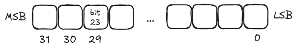
Bit 23—the MSB—of the received 24-bit value ends up in bit 29 of the reconstructed value.
But wait! Why is the offset 2 when SD is supposed to have an offset of 1 with respect to WS? This timing chart shows what happens in the emulation.
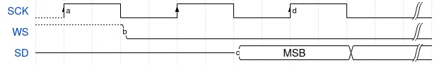
- a - When SCK starts, data is sampled on the leading edge. This corresponds to bit 31.
- b - On the trailing edge of SCK, TI2 detects a falling edge. The timer is started and T1C3 starts generating WS.
- c - INMP411 sends MSB 1 SCK period after WS is driven low. By this time, the DMA has already moved on to bit 30.
- d - On the leading edge of the 3rd SCK, the MSB gets sampled. This corresponds to bit 29. This is why there is an extra SCK in the offset.
(3) To align the data, the value gets right shifted by 6 bits.
(4) The sign bit (bit 23) is checked. If it is 1, the top byte is set to all 1’s to extend the sign and get a 32-bit signed integer.
(5-7) RMS is calculated.
(8) The RMS value is converted to a 16-bit value and used as the duty cycle for the LED’s PWM.
Summary
This is all that is necessary to emulate I2S with SPI and a timer. The setup is straightforward, but aligning the data required careful consideration of where the MSB actually ended up in the data buffer.
👉 The full code to this example is in this Codeberg repository.